How to Choose Rotary Sensors for Your Application?
Rotary Sensors convert shaft movement into usable position, speed, or direction data. Choosing one affects more than measurement accuracy. It can shape control stability, machine uptime, and maintenance needs. A compact encoder on a packaging line may face vibration, dust, and frequent start-stop cycles. A sensor inside a servo motor may need finer resolution and fast, reliable feedback. The right choice depends on the application, not a headline specification.
The International Federation of Robotics reported 4,281,585 industrial robots operating worldwide in 2023, with 541,302 new installations that year (World Robotics 2024). These figures show the scale of automated motion systems, where dependable feedback is essential. They do not, by themselves, prescribe a sensor type. Engineers still need to compare incremental and absolute measurement, resolution, accuracy, response time, interface, mounting space, and environmental protection. A blunt truth: more resolution is not always better. It can add cost without improving the machine’s actual performance.
This guide examines how to match sensor characteristics to real operating conditions. Consider the shaft speed, expected lifetime, electrical noise, temperature, and exposure to moisture or contaminants. Check compatibility with the controller and confirm whether the application requires documented safety performance. Datasheets help, but installation details matter too. A sensor that performs well on a clean test bench may behave differently beside a vibrating motor. The final selection should balance measurable requirements with practical experience—and leave room to verify performance after installation.
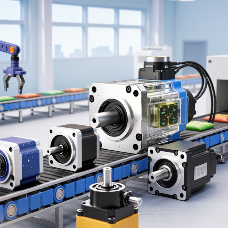
Map Shaft Motion, Speed, and Duty Cycle Before Selecting a Sensor
Before comparing rotary sensors, describe exactly how the shaft moves. Does it turn continuously, or stop and reverse within a fixed angle? Record its travel range, direction changes, and any backlash. A shaft that moves only 90 degrees needs different measurement coverage from one that rotates through several full turns. Small details matter.
Measure speed across normal operation and startup, not just at a steady state. Note the slowest movement, peak revolutions per minute, and how often the shaft accelerates or pauses. Then map the duty cycle: hours per day, starts per hour, and expected service life. A sensor used for occasional adjustment may tolerate different operating demands from one tracking a motor shaft all day. Check the machine’s temperature, vibration, dust, and available mounting space, too. These conditions can shape the choice as much as resolution does.
Use these observations to set a practical resolution and response-time target. More counts per revolution are not automatically better; they can add processing demands without improving the control task. If possible, compare the sensor’s output with a measured shaft position on a test fixture. My first duty-cycle estimate would probably be too neat. Real equipment idles, stalls, and gets adjusted in ways a spreadsheet may miss. Recheck the map against actual operating logs before committing.
Choose Resolution: 12-Bit Encoders Provide 4,096 Positions per Revolution
A 12-bit rotary encoder divides one revolution into 4,096 digital positions. Each step represents about 0.0879 degrees, or 5.27 arcminutes. At a 50-millimeter shaft radius, that step corresponds to roughly 0.077 millimeters of movement along the edge. Small increments matter. They can help a control system make smoother adjustments, but resolution alone does not guarantee precise positioning.
NIST Technical Note 1297 sets out how measurement uncertainty should be evaluated and reported. Apply that mindset when comparing encoder specifications: treat 4,096 positions as digital granularity, not guaranteed accuracy. Shaft runout, mounting alignment, electrical noise, and signal processing can all affect the position you actually measure.
A valve knob may work well with 12 bits; a high-speed motor may also require attention to update rate and latency. Check the complete system. It is easy to focus on the impressive count and overlook how the sensor is mounted. Then test the assembly under real operating conditions, because the theoretical step size may not match what the mechanism can repeat.
Compare Accuracy and Linearity Alongside SSI, CANopen, or 4–20 mA Outputs
A rotary sensor should be judged by how accurately it tracks the shaft across its working range. Check total error, linearity, repeatability, and resolution separately; these figures describe different behaviors. A sensor may offer fine resolution yet drift near the ends of travel. Look for test conditions, too, including temperature and supply voltage. A neat datasheet comparison can still miss the conditions inside your machine.
Tips: Match the output to the controller and cable run. Test with the real wiring, load, and mounting arrangement. Small errors matter.
SSI can provide direct digital position data and suit systems that need predictable updates. CANopen can simplify communication among several networked devices, but confirm supported profiles and update timing. A 4–20 mA output is often practical over longer, electrically noisy runs; check scaling, input resistance, and the controller’s conversion accuracy. Keep the full signal path in view. A sensor’s quoted accuracy does not guarantee the same accuracy at the control screen. Record readings at several shaft positions, then compare them with a trusted reference. That test takes time, and it may expose a mounting issue rather than a sensor fault.
Check Ingress Protection: IP67 Includes 1 m Immersion for 30 Minutes
When choosing a rotary sensor for a damp or dusty installation, read the full IP rating. The first digit 6 indicates dust-tight protection. The second digit 7 covers temporary immersion: typically up to 1 metre of water for 30 minutes under specified test conditions. That matters near splash-prone machinery or equipment that may be briefly submerged. It is not a promise of permanent underwater operation.
A datasheet can make this look settled. It isn’t always. Check whether the rating applies to the complete sensor, including its connector and cable entry, or only to the housing. A poorly seated connector, nicked seal, or stressed cable can create a path for water. Inspect the installation details. Also consider water temperature, cleaning chemicals, and pressure from washdown jets; IP67 alone does not confirm resistance to those conditions. If the sensor will be submerged repeatedly, test the assembled unit in conditions close to the real application and ask the supplier how its rating was verified. A small gap can matter. Recheck seals after maintenance, because wear and handling may change protection over time.
How to Choose Rotary Sensors for Your Application?
IP67 includes a temporary immersion test: up to 1 m of water for 30 minutes.
What this means: IP67 combines dust-tight protection (IP6X) with the IPX7 immersion test. The IPX5 and IPX6 jet-test durations shown are minimums; the required duration may be longer depending on enclosure surface area. IPX7 does not by itself guarantee protection against water jets, so check the specific test requirements for your application.
Verify Safety Needs Against IEC 61800-5-2 and Manufacturer Ratings
Selecting a rotary sensor for a safety-related machine function takes more than matching resolution and shaft size.
IEC 61800-5-2 addresses functional safety for adjustable speed electrical power drive systems. It does not, by itself, certify every sensor or guarantee a safe machine. Define the required function first: safe speed monitoring, position feedback, or another drive-related task. Then identify the target Safety Integrity Level or Performance Level from the machine risk assessment.
Check the manufacturer’s safety data for the exact sensor version and operating conditions. Look for declared SIL or PL capability, diagnostic coverage, failure data, and any required installation limits. A sensor’s rating may depend on how it is connected to the drive and evaluated within the complete safety function. Verify that the wiring, interface, and fault response match the documented setup. Small details matter. A long cable near a motor lead, shaft misalignment, or vibration can affect reliable operation. Confirm temperature, ingress protection, and maximum speed ratings against the real installation, not an ideal bench test. A tidy datasheet can still leave questions. Ask the manufacturer to clarify gaps, and document how the chosen sensor supports the validated system.
